How I test my Windings Efficiency
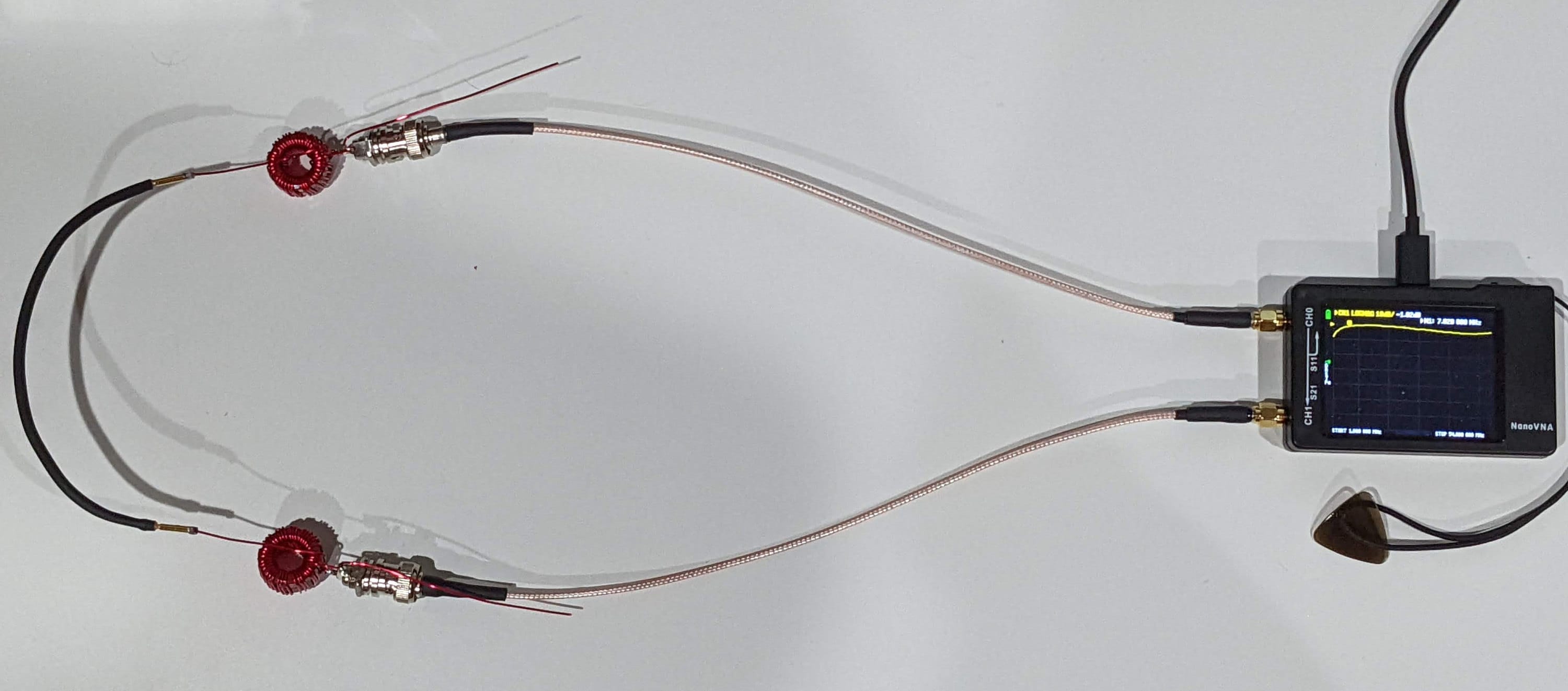
A simple “side-by-side’ method can be deployed with the use of a Calibrated NanoVNA to read back “S21 Gain” which is, in this case, signal loss from the output of S11 back into S21 through the identical windings. The gain (loss) reading in negative dB gives us the total signal loss through the windings. We can then divide by 2 to get the loss through one winding and then convert with a bit of math to an efficiency number.
p = 10^(x/10) * 100 where p = percentage 0-100% and x = loss in dB
Example: -2dB reading on “S21 Gain” on the NanoVNA divide by 2 for a loss of -1dB on each winding would be 10^(-1/10) * 100 = 79.4%
We have a 50 ohm signal coming out on S11 of the NanoVNA through the first winding to some unknown exact impedance but that is then converted back through the second unun into the S21 port where the signal is measured. It is therefore necessary to use identical windings for each test to ideally match the impedance change.

I like to run the signal test with the top and bottom of each band, take the average of the two, and then convert to efficiency, 100% being perfect. I record these values to then chart each band's efficiency for the winding pairs. The goal here is to compare the different windings. For example, with a 9:1 used for a long/random wire, compare toroid sizes, number of toroids and in some cases the number of windings. One nice advantage to a 9:1 Trifilar winding is that you can increase or decrease the winding count in multiples of 3 while maintaining a 3:1 winding ratio. Take the square of the windings ratio (3) to find the impedance ratio of 9:1.
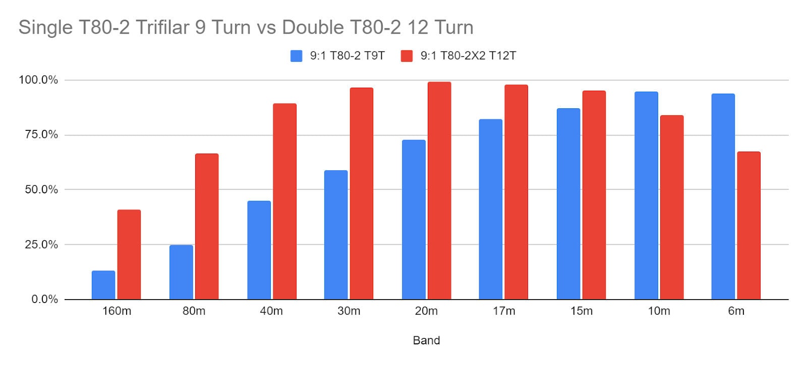
Here is one example of two different windings compared. Both are Trifilar but one with a single T80-2 toroid and 9 sets of turns and the second with a Double T80-2 and 12 sets of turns. 100% would be zero signal loss through the windings, 0% would be full signal loss. -3dB (loss) per winding would equate to a 50% efficiency in either single winding.

The difference between these two windings across the Amature Bands was quite surprising to me. I assume typical, often used windings will be decent across the bands. Here we saw a large improvement in access to the bands by adding several extra turns.
When each component of the station induces loss to the radiated signal, or the ability to receive, you have to improve each area for the best transmit and receive capability. This test is not foolproof, it is not the most accurate way to measure efficiency and maybe not the easiest but it gives me a comparative analysis of various windings with the tools available to me. If I can increase the performance of my windings, I can increase the performance of my station. Time to wind some more transformers!
Joshua
N5FY